Difference between revisions of "Epilog Laser 101"
| Line 29: | Line 29: | ||
#:[[File:Laser 101.07 File - Place.png]] | #:[[File:Laser 101.07 File - Place.png]] | ||
#Navigate to the '''Members folder''' in the root of the C drive. Navigate into the '''Intro To Laser''' folder and select the '''MakerFX Logo.svg'''. | #Navigate to the '''Members folder''' in the root of the C drive. Navigate into the '''Intro To Laser''' folder and select the '''MakerFX Logo.svg'''. | ||
| + | #:[[File:Laser 101.08 File - Place - Locate.png]] | ||
#Hold '''SHIFT KEY''' and then drag a handle of the image to get it to the desired size. | #Hold '''SHIFT KEY''' and then drag a handle of the image to get it to the desired size. | ||
| − | |||
#Don't worry about aligning the image vertically or horizontally. We will fix that next. | #Don't worry about aligning the image vertically or horizontally. We will fix that next. | ||
#Select both the Ellipse and the MFX Logo. Select the first object and hold SHIFT while selecting the second object. The image below is shown when you have both objects selected. | #Select both the Ellipse and the MFX Logo. Select the first object and hold SHIFT while selecting the second object. The image below is shown when you have both objects selected. | ||
#:[[File:Laser 101.09 Align Select Objects.png]] | #:[[File:Laser 101.09 Align Select Objects.png]] | ||
| + | #This step will align the two objects on the '''horizontal axis'''. Select '''File''' -> '''Object''' -> '''Horizontal Align Center'''. | ||
#:[[File:Laser 101.10 Align Horizontal Center.png]] | #:[[File:Laser 101.10 Align Horizontal Center.png]] | ||
| + | #This step will align the two objects on the '''vertical axis'''. Select '''File''' -> '''Object''' -> '''Vertical Align Center'''. | ||
#:[[File:Laser 101.11 Align Vertical Center.png]] | #:[[File:Laser 101.11 Align Vertical Center.png]] | ||
| + | #Save your design before proceeding to the next step. | ||
#:[[File:Laser 101.12 File - Save.png]] | #:[[File:Laser 101.12 File - Save.png]] | ||
| Line 41: | Line 44: | ||
The Epilog laser is connected to the MFX network much like a traditional laser printer. You will be using various print dialogs to configure how the laser will operate for the specific material you are using. | The Epilog laser is connected to the MFX network much like a traditional laser printer. You will be using various print dialogs to configure how the laser will operate for the specific material you are using. | ||
| + | #Select '''File -> Print''' as the first step | ||
#:[[File:Laser 101.13 Adobe File Print.png]] | #:[[File:Laser 101.13 Adobe File Print.png]] | ||
| − | + | #Click the '''Setup''' button to open the standard Windows print dialog. It is normally the default printer on the laser PC. | |
#:[[File:Laser 101.14 Adobe Print Dialog.png]] | #:[[File:Laser 101.14 Adobe Print Dialog.png]] | ||
| − | + | #The Windows printer '''Epilog - NETWORK''' is how Windows knows about the Epilog laser. | |
#:[[File:Laser 101.15 Windows Print Dialog.png]] | #:[[File:Laser 101.15 Windows Print Dialog.png]] | ||
| − | + | #Click the '''Preferences''' button on the right which will open the Epilog Printing Preferences dialog. | |
#:[[File:Laser 101.16 Epilog Printing Preference.png]] | #:[[File:Laser 101.16 Epilog Printing Preference.png]] | ||
Revision as of 14:32, 21 February 2021
This page details the basis of how to create a design via Illustrator and "print" the job to the Epilog laser.
Creating a new Illustrator Artboard
This step is very straight forward and is like creating a new file in any software program you might be familiar with. The critical part of this step is properly setting the dimensions of the material you will place in the laser. NOTE: Failing to properly set the dimensions of your material could result in the laser cutting or etching outside of the intended area.
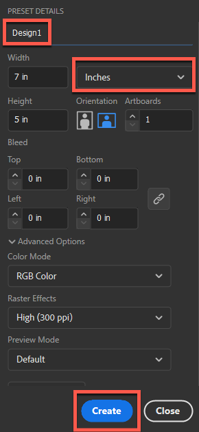
- On the right under Preset Details, you need to enter the details of the material you'll be using. The image below shows the most important settings:
- ITEM 1: Name of your design. IE: Design1
- ITEM 2: Unit of measure. IE: Inches
- ITEM 3: Width and Height of your material. IE: 7 inches width and 5 inches height.
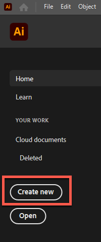
- When you are done setting up your job, click the Create button. The Job Setup panel will close and you will be shown a blank Illustrator design screen which is called an Artboard.
Creating your design
- This step involve using a variety of toolbars within Illustrator. The main toolbar is usually docked on the left and is called the Advanced Toolbar.
- We are making a large keychain tag. Select the Ellipse tool on the Advanced toolbar
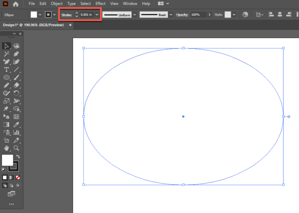
- Use the mouse and draw out an ellipse as shown below
- Select the ellipse and then set the Stroke width to 0.001 inches. You will see the Stroke width highlighted in the red box below.
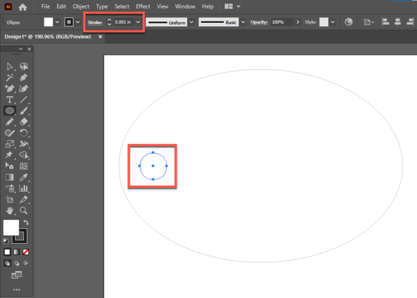
- Illustrator does not have a dedicated circle option. You use the Ellipse tool and just hold the SHIFT KEY to draw a small circle on the left side of the ellipse.
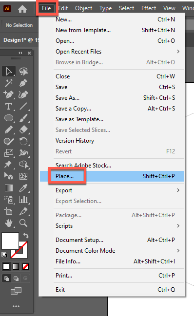
- The next step involves placing an image on our keychain tag. In this example we are placing a SVG file but the same process can be used for placing other types of files such as JPG, PNG or DXF files.
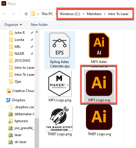
- Navigate to the Members folder in the root of the C drive. Navigate into the Intro To Laser folder and select the MakerFX Logo.svg.
- Hold SHIFT KEY and then drag a handle of the image to get it to the desired size.
- Don't worry about aligning the image vertically or horizontally. We will fix that next.
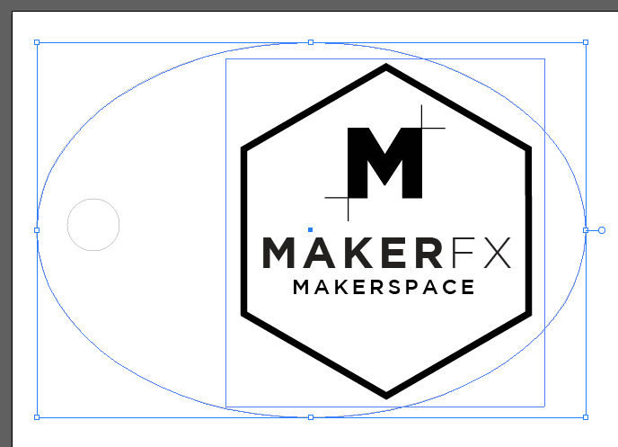
- Select both the Ellipse and the MFX Logo. Select the first object and hold SHIFT while selecting the second object. The image below is shown when you have both objects selected.
- This step will align the two objects on the horizontal axis. Select File -> Object -> Horizontal Align Center.
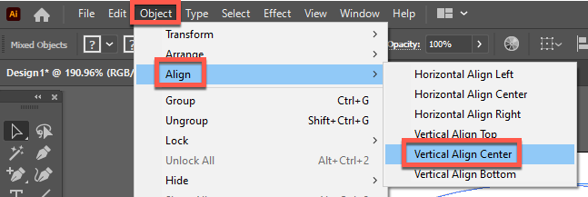
- This step will align the two objects on the vertical axis. Select File -> Object -> Vertical Align Center.
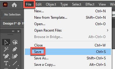
- Save your design before proceeding to the next step.
Configure Design for Laser
The Epilog laser is connected to the MFX network much like a traditional laser printer. You will be using various print dialogs to configure how the laser will operate for the specific material you are using.
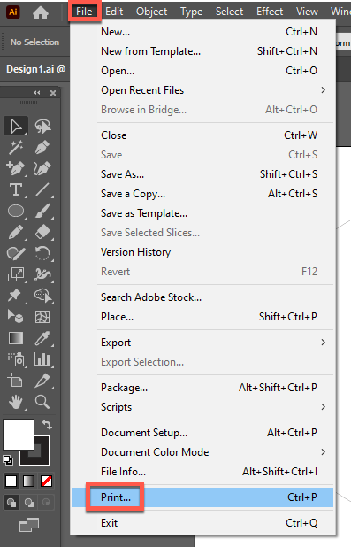
- Select File -> Print as the first step
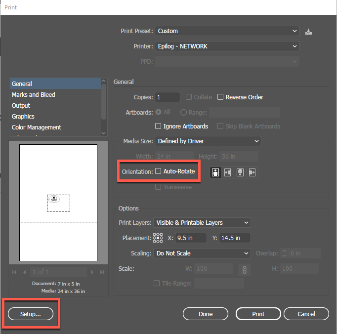
- Click the Setup button to open the standard Windows print dialog. It is normally the default printer on the laser PC.
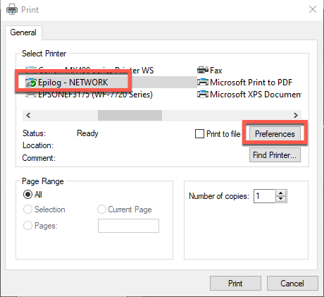
- The Windows printer Epilog - NETWORK is how Windows knows about the Epilog laser.
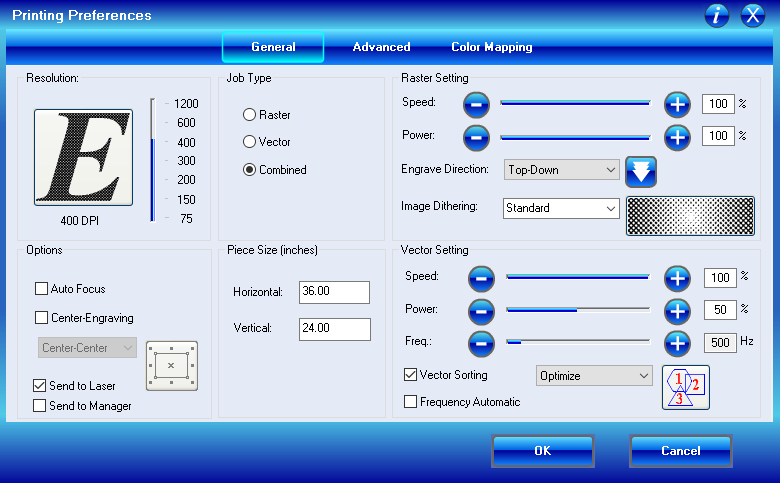
- Click the Preferences button on the right which will open the Epilog Printing Preferences dialog.
