Difference between revisions of "VCarveTutorial"
(→Creating the Toolpaths) |
|||
| Line 40: | Line 40: | ||
== Creating the Toolpaths == | == Creating the Toolpaths == | ||
| + | Once your design is done, you need to create the Toolpaths, or the instructions the CNC will use to mill your object. Depending on the complexity of your design, you may only need one toolpath or you may need several. Each toolpath defines parameters such as: | ||
| + | * The type of bit that will be used | ||
| + | * The speeds and feeds of the cut | ||
| + | * The depth of the cut | ||
| + | * The pattern the tool should follow. | ||
| + | To setup a tool path: | ||
| + | # Select the object or objects you wish to be a part of this path. You can select multiple object by SHIFT + Left Clicking each object. CTRL + A selects them all. | ||
| + | # If it is not already expanded, click on the '''Toolpaths''' panel in the upper right corner of VCarve. | ||
| + | # There are several different types of Toolpaths you can use. For this tutorial we'll use the Pocket Toolpath by clicking on it. | ||
| + | #: [[File:XCarvePocket.png]] | ||
| + | # From the ''Pocket Toothpath'' settings panel, we can | ||
== Saving your GCode == | == Saving your GCode == | ||
Revision as of 17:21, 25 July 2017
Contents
Overview
VCarve is one of the many tools you can use to create designs for the X-Carve CNC. MakerFX has a fully functional Makerspace edition of VCarve Pro on the CNC controller computer which is available for members for use. To learn more about VCarve, visit their website.
Tutorial
This is a very simple tutorial will demonstrate how to use the CNC to design a file that will cut two "channels" for t-track from a piece of lumber, from creating a new VCarve file through preparing the GCode for the CNC to use. This tutorial is broken down into the following sections:
- Creating a new VCarve Job
- Drawing your designs
- Creating the Toolpaths
- Saving your GCode
Creating a new VCarve Job
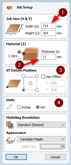
This step is very straight forward and is like creating a new file in any software program you might be familiar with. The critical part of this step is properly setting the dimensions of the material you will be milling. NOTE: Failing to properly set the dimensions of your material could result in damage to your project, the bit or to the machine!!!
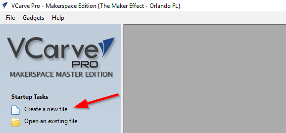
- Open VCarve using the shortcut on the desktop
- Either open an existing model, or create a new one. For this tutorial, we'll create a new one.
- From the JOB SETUP panel, you need to enter the details of the material you'll be using. The image below shows the most important settings:
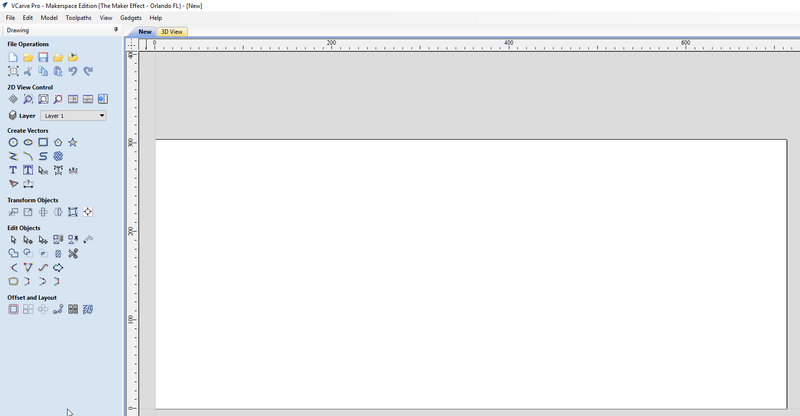
- When you are done setting up your job, click the OK button. The Job Setup panel will close and you will be shown a blank VCarve design screen.
Drawing your designs
Once your file has been created, it is time to start your drawing. For this tutorial, we need to carve two grooves into the wood for t-track. The t-track is 12.446 mm deep and 18.542 mm wide. VCarve provides a variety of tools to draw and modify shapes. To draw our grooves, we'll:
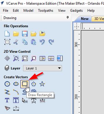
- Start by selecting the Rectangle Vector tool
- Next, draw a rectangle anywhere on the drawing that represent where we want the grooves to be milled. The placement or size doesn't matter in this step.
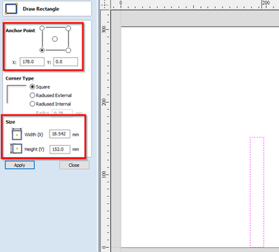
- To accurately size and place the grooves, we can use the fields in the Draw Rectangle panel.
- The X and Y values at the top under the Anchor Point setting allows you to set the X and Y position of the object. In this case, we want the object to be about 1/4 of the way from the left edge and bottom aligned. Since the Anchor Point is set to the lower left corner, to achieve this we need to go in 178 mm on the X axis and 0 for the Y axis.
- The size of the groove can be set using the Size settings, specifically the Width (X)' and Height (Y) fields. The width of the t-track is 18.542 mm and we want to run 1/2 way down the wood, or 152 mm.
- Once finished, hit the Create button to draw your object.
- Create another rectangle of the same dimensions, but for this one, set the X / Y coordinates to 535 and 0 to have the second track about 1/4 way in from the other side of the material.
Creating the Toolpaths
Once your design is done, you need to create the Toolpaths, or the instructions the CNC will use to mill your object. Depending on the complexity of your design, you may only need one toolpath or you may need several. Each toolpath defines parameters such as:
- The type of bit that will be used
- The speeds and feeds of the cut
- The depth of the cut
- The pattern the tool should follow.
To setup a tool path:
- Select the object or objects you wish to be a part of this path. You can select multiple object by SHIFT + Left Clicking each object. CTRL + A selects them all.
- If it is not already expanded, click on the Toolpaths panel in the upper right corner of VCarve.
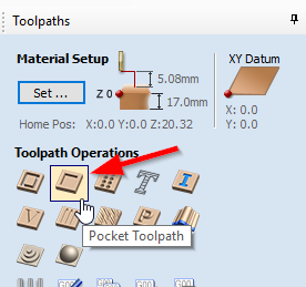
- There are several different types of Toolpaths you can use. For this tutorial we'll use the Pocket Toolpath by clicking on it.
- From the Pocket Toothpath settings panel, we can
